

Product Overview
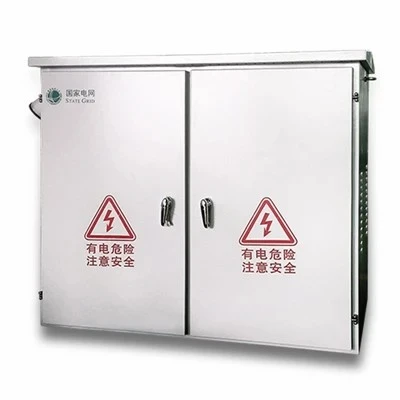
The Automatic Transfer Switch (ATS) Panel manages power switching between a primary utility grid and an emergency standby generator. It continuously monitors incoming voltage and frequency. Upon utility voltage drop or phase loss, the system initiates a generator start signal and transitions the electrical load automatically. When normal utility power stabilizes, it retransfers the load back and initiates generator cool-down and shutdown.
Engineered for continuous duty in heavy commercial and industrial electrical distribution, the assembly incorporates mechanically and electrically interlocked switching devices to eliminate the risk of parallel grid-generator feeds. Enclosures are fabricated from heavy-gauge structural steel, configured for wall-mounting or floor-standing lineups based on current capacity and cable entry requirements.
Technical Specifications
|
Parameter |
Standard Specification Options |
|
Rated Operational Voltage (Ue) |
400V AC (3-phase 4-wire), 480V AC, up to 690V AC |
|
Rated Current (In) |
63A to 3200A |
|
Pole Configuration |
3-Pole (3P) / 4-Pole (4P) with 100% rated neutral switching |
|
Transfer Mechanism |
Dual-motor motorized circuit breakers / Dual contactors with mechanical interlock |
|
Transfer Time |
<100 ms (programmable transition delay available) |
|
Short-Circuit Withstand (Icw) |
35kA to 85kA (1s) |
|
Controller Interface |
Microprocessor-based digital controller with backlit LCD; Modbus RTU / TCP, SNMP communication ports |
|
Enclosure Protection |
IP30 to IP54 (Indoor); NEMA 3R / NEMA 4X (Outdoor powder-coated carbon steel or stainless steel) |
|
Design Standards |
IEC 60947-6-1, IEC 61439-2, GB/T 14048.11 |
Key Features
Dual-Interlock Architecture: Physical mechanical linkages combined with auxiliary electrical contact cut-offs prevent phase-to-phase short circuits during source transition.
Microprocessor Logic Control: Field-adjustable timers govern engine start delay (0-30s), transfer to emergency (0-60s), retransfer to normal (0-30min), and generator cool-down (0-30min).
Active Source Monitoring: Tracks phase loss, under/over-voltage (±5% - 30% adjustable), under/over-frequency, and phase sequence imbalance on both normal and emergency supplies.
Manual Emergency Override: Padlockable mechanical operation handle permits direct manual transfer independent of control power or automatic logic failure.
Isolated Neutral Pole: Four-pole configurations ensure complete switching isolation of neutral lines to prevent circulating currents in grounded multi-source distribution networks.
Applications
Data Centers & Telecommunications: Secures continuous uptime for server racks, networking gear, and remote cell towers by bridging grid dropouts instantly.
Healthcare & Life Safety: Meets stringent regulatory mandates for operating rooms, intensive care units, and critical emergency egress circuits.
Industrial Manufacturing: Prevents assembly line downtime, hardware damage, and PLC data corruption during municipal power fluctuations.
Commercial Real Estate: Powers building life-safety infrastructure, including fire booster pumps, smoke extraction fans, and emergency stairwell lighting.
Customization
Engineering modifications align directly with project single-line diagrams (SLDs) and regional switchgear specs:
Enclosure Footprint: Custom dimensions, modular shipping splits, bottom or top cable entry gland plates, and internal layout revisions for brownfield retrofits.
Component Brand Integration: Specification of upstream/downstream circuit breaker and contactor brands (Schneider, ABB, Siemens, or equivalent project-approved makes).
Communication Gateways: Integration of BACnet, Profibus, or Ethernet modules for centralized building management systems (BMS) or SCADA monitoring.
Auxiliary Protection: Inclusion of Type 1/2 Surge Protection Devices (SPDs), harmonic filters, dual-metering power analyzers, or internal thermostat-controlled enclosure anti-condensation heaters.
Manufacturing & Quality Control
Fabricated in a 15,000-square-meter production facility utilizing CNC laser cutting centers, CNC press brakes, and automated busbar punching and bending machines. Enclosure carbon steel panels undergo a multi-stage iron phosphating pretreatment followed by automated electrostatic powder coating, achieving salt spray corrosion resistance exceeding 500 hours (ASTM B117).
Every assembled ATS panel undergoes rigorous Factory Acceptance Testing (FAT) prior to crating:
Dielectric Withstand Test: 2.5kV applied at 50Hz for 1 minute across live conductors and grounded frame.
Insulation Resistance Test: Verified using a 1000V megohmmeter (>= 100MΩ).
Logic Simulation Test: Full functional validation of controller trip thresholds, timer sequences, and interlock signal loops under simulated low-voltage inputs.
Busbar Joint Verification: Micro-ohm meter resistance testing on all primary bolted busbar joints to verify torque integrity and prevent thermal hotspots.
Certifications & Documentation
Compliance: Manufactured in adherence to IEC 60947-6-1 (Automatic transfer switching equipment) and IEC 61439-2 (Low-voltage switchgear and controlgear assemblies).
Documentation Package: Each shipment includes electrical schematic wiring diagrams (CAD/PDF formats), bill of materials (BOM), controller operation manuals, individual FAT test reports, and raw material certificates (copper purity reports, breaker calibration sheets).
Packaging & Delivery
Export Crating: Panels are bolted to fumigation-free wooden export pallets, sealed in moisture-barrier anti-corrosion polyethylene film with desiccants, reinforced with corner edge protectors, and enclosed in heavy-duty plywood crates.
Rigging Provisions: Supplied with removable top-mounted lifting lugs and integrated forklift base channels for safe handling on job sites.
Lead Time: 2 to 3 weeks for standard stock-tier configurations; 4 to 6 weeks for custom-engineered switchgear systems.
FAQ
Hot Tags: automatic transfer switch panel, China automatic transfer switch panel manufacturers, suppliers, factory