

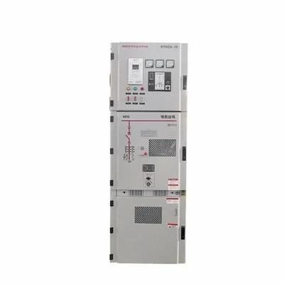
Product Overview
The Withdrawable Motor Control Center centralizes motor starters, feeders, and power distribution circuits within a modular metal-enclosed assembly. Engineered for continuous process industries requiring zero-downtime maintenance, it utilizes plug-in functional drawer units that enable operators to isolate, remove, and service individual motor circuits while main horizontal and adjacent feeder buses remain energized.
Technical Specifications
|
Parameter |
Specification Range |
|
Rated Operational Voltage (Ue) |
Up to 690V AC, 50/60 Hz |
|
Rated Insulation Voltage (Ui) |
Up to 1000V AC |
|
Main Busbar Rated Current (In) |
Up to 6300A |
|
Short-Time Withstand Current (Icw) |
Up to 100kA for 1s |
|
Internal Separation Form |
Form 3b to Form 4b (IEC 61439-2) |
|
Enclosure Protection Rating |
IP30 to IP54 (Up to IP54 with gasketed options) |
|
Drawer Functional Unit Sizes |
1/2M, 1M, 2M, 3M modular heights |
|
Busbar Conductivity & Purity |
T2 Electrolytic Copper (Purity >= 99.9%, Conductivity >= 56 MS/m) |
|
Surface Treatment |
Electrostatic epoxy-polyester powder coat, RAL 7035 / RAL 7032 |
Key Features
Positive Triple-Position Mechanism: Each functional drawer features absolute mechanical detents for Connect, Test, and Disconnect/Isolated states, featuring padlocking options in the isolated position to prevent unauthorized re-racking.
Foolproof Mismating Interlocks: Mechanical coding pins on the chassis and drawer frame prevent inserting a functional unit into a slot with mismatched voltage, control logic, or ampacity ratings.
Self-Aligning Silver-Plated Contacts: High-pressure spring-loaded plug-in primary and secondary connectors maintain low contact resistance (< 0.1 mOhm) and withstand repeated insertion cycles under high thermal expansion stress.
Compartmentalized Arc-Fault Containment: Main horizontal and vertical busbars are enclosed in high-strength, arc-resistant, flame-retardant PVC chambers to restrict internal fault propagation.
Predictive Thermal Monitoring: Integrated fiber-optic or wireless temperature sensor tags track busbar joints and cable termination points, streaming real-time thermal data directly to plant SCADA networks.
Applications
Oil, Gas & Petrochemical Refineries: Continuous-duty crude oil booster pumps, high-pressure compressor trains, and auxiliary processing units requiring zero planned outage during servicing.
Municipal Water & Wastewater Plants: Raw water intake pump stations, high-lift booster networks, and automated sludge dewatering control systems.
Heavy Metals & Mineral Processing: High-vibration environments including heavy conveyor drive lines, industrial ball mills, and primary ventilation exhaust arrays.
Critical Data Center Infrastructure: Auxiliary diesel generator distribution rooms, high-capacity chiller plant HVAC, and UPS downstream sub-distribution switchgear.
Customization
Busbar Architecture: Single or dual busbar configurations (with or without motorized or manual bus couplers) engineered for automatic source transfer and system redundancy.
Control & Communication Integration: Hardwired auxiliary interlocks or intelligent network interfaces supporting PROFIBUS DP, PROFINET, Modbus TCP, Modbus RTU, and IEC 61850 protocols.
Enclosure Mechanical Footprint: Standard depth modules ranging from 600mm to 1200mm, featuring top, bottom, or rear cable entry options with removable gland plates.
Switchgear Component Integration: Main air circuit breakers (ACBs), molded case circuit breakers (MCCBs), contactors, and electronic motor protection relays matched to project-specified tier-1 vendor preferences (Schneider Electric, ABB, Siemens, Eaton, or equivalent).
Manufacturing & Quality Control
Sheet Metal Fabrication: Enclosure frames are processed via high-speed CNC laser cutting and multi-axis bending cells, maintaining strict assembly dimensional tolerances within +/- 0.5 mm to ensure flawless drawer guide-rail alignment.
Busbar Workshop Processing: Electrolytic copper busbars are cut, punched, and bent on automated CNC tooling, deburred, and torqued using traceable digital calibration tools to verify correct clamping pressure.
Routine Factory Testing (FAT): Every assembled section undergoes 2500V dielectric voltage withstand testing for 1 minute, primary/secondary wiring continuity checks, mechanical interlocking verification, and multi-cycle drawer racking tests.
Certifications & Documentation
Type Testing Compliance: Designed and tested in strict accordance with IEC 61439-1 and IEC 61439-2 standards, supported by verified short-circuit and temperature-rise test certificates from ILAC-accredited laboratories.
Seismic Qualification: Available configurations compliant with IEEE 693 and IBC seismic acceleration standards for harsh geographical zones.
Turnover Documentation: Shipments include as-built EPLAN Electric P8 schematics, 3D STEP layout models, component bills of materials (BOM), and individual factory test sheets.
Packaging & Delivery
Export-Grade Protection: Sections are bolted to heavy-duty fumigated wooden shipping skids, wrapped in anti-corrosion VCI (Volatile Corrosion Inhibitor) film, and sealed with moisture-absorbing silica gel packs.
Site Rigging Optimization: Configured in modular shipping blocks (typically 3 to 4 vertical sections per skid) with integrated top lifting lugs to streamline container offloading and crane rigging on site.
FAQ
Hot Tags: withdrawable motor control center, China withdrawable motor control center manufacturers, suppliers, factory